Fixing a leaking fill valve. Replaced an old Fluidmaster valve with a new (and way better) Korky valve.
Saturday, October 3, 2015
Tuesday, September 1, 2015
Sunday, June 28, 2015
Guest Post - A/C Unit
Taking a break from media room posts. Today, we have another guest post from Eric about maintaining your A/C Unit.
-------------------------------------------------------------------
With the unusually hot weather in the southeast this summer, I thought it would be a good idea to do a quick check on my central A/C unit. There are several things you can look at when doing a quick check of your system but today I'm going to focus on the refrigerant line going to your compressor.
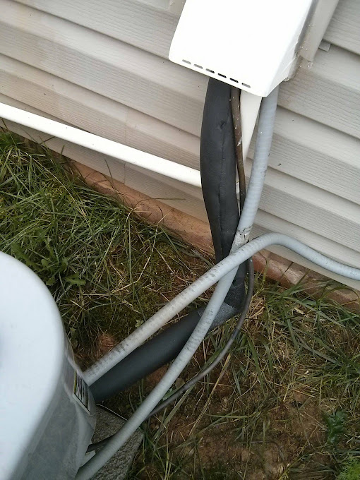
Central air conditioning systems operate by circulating coolant through an indoor coil (i.e. the evaporator coil) which absorbs heat and moisture from the hot nasty air insider. The refrigerant then flows outside to the condenser coil where heat is released through radiator fins. The cold coolant then flows back indoors where it absorbs all the heat from inside your house. For you nerds out there, it is nothing more than a heat exchange unit that utilizes the heat capacity of coolant and the high surface areas of evaporator coils and radiator fins to maximize heat exchange. Therefore, you can see why it would be important that the cold coolant line flowing back into the house be well insulated so it is as cold as possible. This is how mine looked the other day (the black line is the refrigerant line):
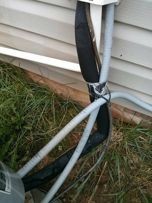
Pretty bad right? Portions of the insulation have split altogether and exposed the piping underneath. Overall, the material is cracked and deteriorated from baking in the North Carolina sun for who knows how long. Also, I'm not sure why all those lines are tied together with a combination of gaffer tape and tie wraps. That's just ugly and unnecessary.
Before you start, peel back a little of the refrigerant line so you know the diameter of the piping. Buy the right insulation for your piping. I think mine was 7/8" or something.
First, turn off the air conditioning unit at the breaker or the thermostat. It isn't too important because we aren't going near any moving parts but we want the refrigerant line to come up to ambient temperature so no condensation forms during the next step, which is removing the old insulation. Cut it all off. Throw it out. Look how nasty it is. Gross.
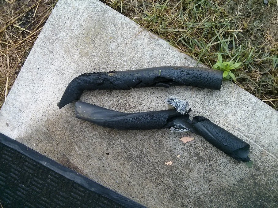
Clean your refrigerant line off and make sure it is dry. If you install new insulation over a wet line, you'll trap moisture inside and hasten deterioration of the insulation. Next, put on the foam elbows at any bends in your piping. At hardware stores, you can find these elbow joints for a few dollars. This one cost $3 which sounds pricey for a small piece of foam but they are worth it! Trying to bend a tube of foam into a right angle is futile but these little pieces fit perfectly!
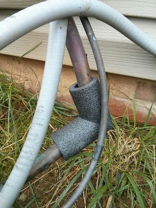
Next, measure your lengths of piping and cut your new insulation to fit. For lines running parallel to the ground, install them with the seams facing down. This is important because any moisture that accumulates inside the insulation can then drip down through the seam. Trapped moisture is your enemy here.
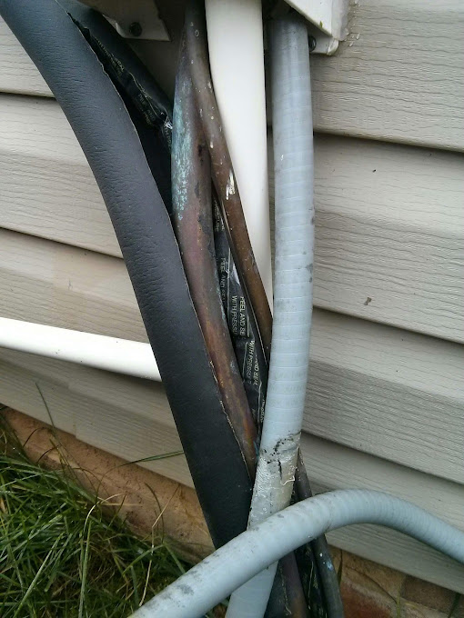
Things got tricky here with the suction, condensate, and piping lines all joining. Use some elbow grease to fit that tubing over and then remove the plastic covering the adhesive. Hopefully, your builders did a better job than mine. This is just ugly.
There, all done. Something is missing right? It doesn't make sense to have black insulating foam bake in the sun, exposed to the elements, etc. I decided to wrap the insulated line in reflective tape being sure not to tape over the seams. I used normal foil tape that you can find at any hardware store.
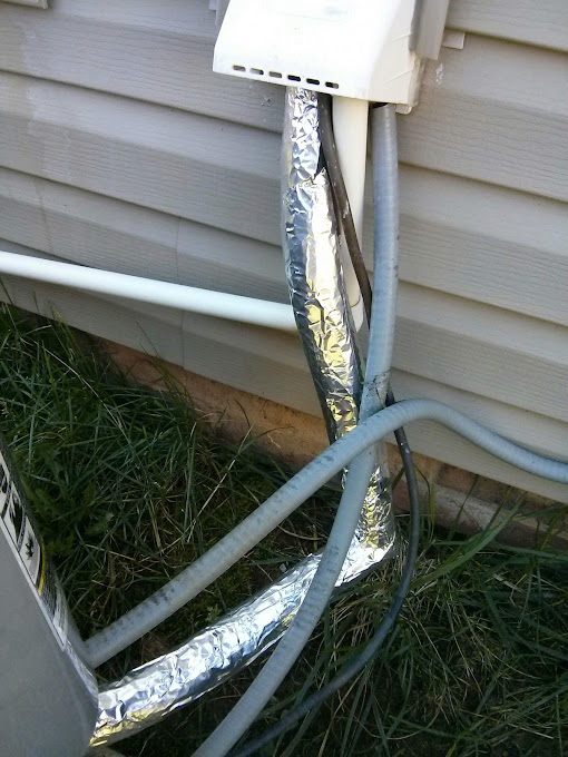
And that's it! This is a pretty easy and cheap DIY. 6 feet of insulating foam cost $6, the elbow was $3, and a 30 foot roll of foil tape was $4. Thanks Charles for letting me do this guest post.
Sunday, June 14, 2015
Cutting Drywall
One of the core skills I had to learn for setting up the media room was how to cut drywall. Anytime you want to install anything into your wall, you'll have to cut drywall. Here's the easy way to do it.
1. Figure out where you want the installation to go and then trace/stencil the installation onto the wall with a pencil. This will give you a general idea of the size and fit on the wall. Make sure to level out the installation before stenciling. In this post, I'm showing a rectangular cut, but the same process can be used for a circular cut.
3. Take a 1/2 inch drill bit and drill two holes at opposite corners of the stenciled area.
4. Use a drywall saw to cut the stencil. Start at one of the drilled holes and cut towards the stencil line. Then level out the saw at the stencil. Cuts shown in red.
5. Reverse the saw along the stencil to cut out any remaining portions. Cuts shown in green.
Sunday, June 7, 2015
Mess of Wires
Our media room was pre-wired for 7.1 audio. This meant that audio wires were pulled behind the walls and ceiling to where the speakers were going to be. The other ends of the wires collected at one point where the audio receiver was to be placed. The wires weren't labeled though. So at first, the media room just had a mess of wires coming out of the wall. It looked sort of like this:
The first task in setting up the media room was to figure out which wires went to which speaker. Because the wires went behind the walls, it wasn't a simple task. No need to buy a fancy wire tester though. You can test each wire with a AA battery and a flashlight bulb.
At its core, speaker wire is just two copper wires bound together in one housing. This means that you can hook the AA battery up to the two wires at one end and the flashlight bulb at the other end, and the bulb should light up.
First step is to strip the external housing and then strip the individual housing on each speaker wire. After the copper cores are exposed, you can hook up a battery and bulb to either end of the wire. If you have chosen the correct wires, the bulb will light up. Below is a diagram:
Through a series of trial and error, you can figure out which wire goes to which speaker. Label each wire so you don't have to repeat the test.
Sunday, May 24, 2015
The Big Reveal
Not many posts from me the past few months because of baby and because of the media room project. When we bought the house, it came with a prewired media room. Too bad it was just an empty room with wires in the wall.
I wanted to set the room up without hiring out so I could learn some new skills. I went with a 7.1 in-wall system with ceiling mounted projector I've been working on this project off and on for the past 6 months, and it is finally complete. In the picture above, you can see the screen, the two in-wall front speakers, the center speaker, sub, receiver, console, and Frozen.
I'll make more posts later about each mini-project in the media room.
Wednesday, May 6, 2015
Guest Post - Push Mower
Today's entry is a guest entry from Eric in NC about maintaining your push mower.
---------------------------------------------------
If your push reel mower isn't cutting the grass like it used to, one likely culprit is the blades not being properly set. Here's a quick way to check to see if this is the case. First, raise the height of the mower to the tallest setting. This makes getting at the blades easier:
First, push down on the rotary blades to simulate the cutting motion. You should feel no resistance and it should spin freely. If the rotary blades touch the stationary blades, you'll hear a metal on metal noise and this could be the reason why your mower is very difficult to push. If this happens, adjust the blades so that they are as close together without actually touching.
If you find that your blades spin freely, take a strip of paper and position it in between the stationary and rotary blades like so:
If the paper does not get cut, you'll want to position the blades closer together. This is done different on each mower but what you'll be doing is adjust it little by little until the blades actually touch (you'll hear the noise when the rotary blade spins), and then back off the tiniest amount so that there's a tiny bit of space separating the two blades.
This is how it's done on my Fiskars mower. Now go out and enjoy your newly adjusted mower!
Monday, February 9, 2015
Ethernet Ports
One of the things that I wanted to do as I was setting up the home theater was to activate some of the ethernet ports around the house. When our cable was installed, Verizon only activated one of the ports, so many of the ports (including the one in the theater) did not work. I didn't take any pictures during the project, but I have some pictures of the end result.
Find the junction box in your home. Most of the time, the box is located in your master closet or garage. The picture above is our junction box in our master closet. Sometimes the box will be installed onto the wall so it will look like an actual box. Sometimes the box will be installed into the wall so it will look like a metal panel (as pictured above).
Step Two - Input Signal
Open the box or remove the metal panel. This is what the inside of our junction box looked like after I was done hooking everything up. The black/red thing at the bottom was the modem/router that Verizon provided. Our junction box included an A/C outlet to power the modem/router. I had to use an extension cord because the A/C adapter for the modem/router would not fit into the junction box if I plugged it directly into the A/C outlet.
The white wires running down the right side are the coax cables that run to the different coax ports throughout the house. One of the coaxes is a line to the exterior cable box. That coax is fed into a splitter that splits the cable signal into a TV cable signal and an Internet signal.
The Internet signal is fed into the modem/router.
Step Three - Output Signal
The last step is to connect the ethernet ports throughout the house to the modem/router. The junction box contains a box where all the ethernet ports connect to. As you can see in the picture, the yellow CAT5 cables run from the various ethernet ports in the house to jumpers on the box. These jumpers then connect to ethernet ports on the bottom of the box. To activate the ports, I run CAT5 cables from these ethernet ports to the modem/router.
Notes
If your cable company provided only a modem rather than a modem/router combo, do not purchase a router to stick in the junction box with the modem. That would take up a lot of space and cost more than you really should be paying. Instead of buying the router, buy a switch or a repeater. Switches are typically a much smaller form factor and cost much less than a router. Connect the switch to the modem and then connect the ethernet ports on the switch to the ethernet ports on the box.
You will probably need another router to establish a WiFi network throughout your house. Luckily, I had one lying around. It's a bit outdated, so I ordered a new router, which should come in the next few days. In the meantime, my speeds are capped by the old router.
Subscribe to:
Comments (Atom)


